Control Cable Assemblies
Control cable assemblies are used in numerous applications requiring the transmission of force. Especially if the force needs to be routed around bends in varying directions. Some industries that use control cable assemblies and wire pull rope are: Aircraft, Lawn and garden, Exercise equipment, Medical, Automotive, and Office equipment.
Choosing The Right Push-Pull Controls
Choosing the right control cable assembly is a crucial part of the designing and engineering of mechanical components and analog systems. Push pull control cables activate equipment by transmitting physical force through machinery. Though push pull cable operation may seem easy and effortless, there is a great deal of engineering knowledge and experience that is required to design the proper push pull control cable and pull cables to fit an application exactly.
The first consideration, regarding control cables and push pull cables, is the type of treatment they must endure and withstand in the harshest of conditions. To ensure the best and most reliable performance, Tyler Madison manufactures the highest quality wire rope in the assembling, manufacturing, and producing their control cable assemblies, which are tested multiple times to guarantee exceptional performance and durability.
Types of Control Cable Assemblies
Control cable assemblies come in two types, Push-Pull cable assemblies and Pull assembles.
Push-Pull Assemblies
Push-Pull assemblies are used when the transmission of force is required in both directions of the assembly travel. A choke cable assembly on a lawn mower engine is a good example of a push-pull assembly.
Pull Assemblies
Pull assemblies are used when the transmission of force is needed in one direction. A hood release is a good example of a pull assembly.
Push Pull Design Criteria:
When designing a control cable assembly or push pull conduit, some factors to consider are:
- The amount of force needed to be transmitted, or workload factor.
- Routing of the assembly, with special attention to bend radii, and how the assembly will be anchored.
- The length and diameter of the inner wire and the conduit, and the amount of travel required.
When designing a push-pull cable assembly, the workload in the push mode is potentially critical. As the moving inner wire meets resistance, the wire could possibly distort or buckle, especially the portion of the inner wire that extends from the conduit. By increasing the inner wire diameter you can increase the workload in the push direction. A push-pull wire rope assembly is stiffer by nature; therefore, larger bend radii are required for smooth motion of the inner wire.
When designing a pull assembly, the workload is a function of the breaking strength inner cable tempered with a safety factor. The inner push pull cable conduit for pull assemblies can be much more flexible, allowing tighter bend radii when routing the assembly.
Push Pull Inner Wire
When thinking about the inner wire to use in your push pull control cable, there are a number of options to consider. Even the lightest type of load requires a solid wire with core materials that are designed to fit the application. It is important to know that loads are the greatest in the pull direction, which is a major consideration when a push pull cable is being designed.
- Cable Material: Galvanized steel or stainless steel
- Cable Construction: Typically, these assemblies are made of 7 x 19 (most flexible), 7 x 7, or 1 x 19 (least flexible) cables
- Conduit: Most often our customers will opt for uncoated cable as it will create the least amount of friction inside the conduit, and will extend the life of the control.
- Length: There really isn’t a minimum or maximum length, just let us know your application
- Ends Fittings or Terminals: We have a large selection of end fittings, including balls, ball shanks, sleeves, stamped eyes, stops, thimbles, handles/knobs, strap forks, strap eyes, and threaded studs. Others options are available as well.
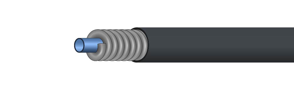
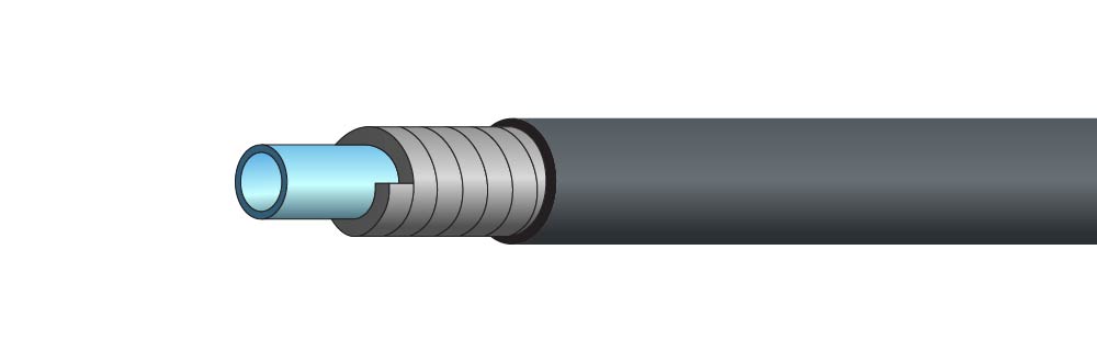
Conduit Bowden Options
Cover: Vinyl, HDPE or uncovered wound wire
Liner: HDPE, or unlined
Braid: wound music wire, or braided and encased in polymer coating
Choosing Conduit Cable
When it comes to control cable assemblies, the quality of the conduit used can make or break the functionality and durability of the finished product. At Tyler Madison, we take pride in offering premium Bowden conduit that outperforms standard alternatives on the market.
Types of Conduit
Conduits come in various styles, each tailored to specific uses.
Bowden-Style Conduit
Known for its exceptional flexibility and durability, Bowden-style conduit is specifically designed for control cables, ensuring precision and consistent performance.

Braided Conduit
Features an internal braided layer for added strength and resistance to crushing, ideal for heavy-duty applications.
Flat-Wound Conduit
Offers a flat, coiled structure that provides excellent flexibility and compressive strength, commonly used in applications requiring tight bends.
Other Design Considerations
You should also consider the following details when designing either style of assembly.
Mounting
How the assembly is mounted to reduce the conduit deflecting under tension. Using clamps and /or end fitting to properly secure the assembly is important.
Loss of Motion
This is another potential problem and can be caused by two variables. One is the deflection of the conduit under tension. Second is relative to the total amount of direction change and the clearance between the ID of the conduit and the OD of the core cable. Due to this loss of motion, the length and diameters of the assembly’s conduit and inner wire are understandable important considerations. One inch travel on the input side of an assembly, does not necessarily mean one inch travel on the output side
Our engineering staff would be more than happy to assist you with your push-pull cable conduit or other push-pull cable design ideas. Depending on application, we may be able to supply a sample to assist in your designing process.
Conduit End Fitting Examples